Mastering AutoCAD: A Comprehensive Guide to Creating and Editing Hatch Patterns
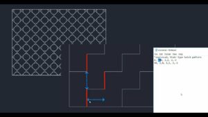
In the realm of computer-aided design (CAD), hatch patterns play a crucial role in depicting various materials, textures, and surface...
In the realm of computer-aided design (CAD), hatch patterns play a crucial role in depicting various materials, textures, and surface...
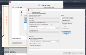
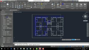
In the world of computer-aided design (CAD), the ability to publish drawings in AutoCAD is paramount for sharing, distributing, and...
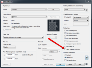
In the domain of computer-aided design (CAD), configuring plot settings in AutoCAD is a pivotal skill that empowers designers, architects,...
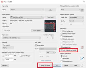
In the realm of computer-aided design (CAD), setting up a plotter in AutoCAD is a fundamental step for generating physical...
In the realm of computer-aided design (CAD), the ability to effectively plot and print drawings is essential for bringing designs...
AutoCAD, the premier computer-aided design (CAD) software developed by Autodesk, offers a wide array of tools and commands for creating...
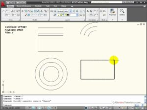
AutoCAD, the leading computer-aided design (CAD) software developed by Autodesk, offers a wide range of tools and commands for creating...