Mastering the OFFSET Command in AutoCAD: A Comprehensive Guide
AutoCAD, the leading computer-aided design (CAD) software developed by Autodesk, offers a wide range of tools and commands for creating precise and detailed drawings. Among these tools, the OFFSET command stands out as a fundamental feature for creating parallel lines, polylines, and curves at a specified distance from existing objects within a drawing. In this comprehensive guide, we delve deep into the intricacies of using the OFFSET command in AutoCAD, exploring various methods, techniques, and best practices for optimal utilization.
Understanding the OFFSET Command in AutoCAD:
The OFFSET command in AutoCAD allows users to create parallel copies of lines, arcs, circles, polylines, and other geometric entities at a specified distance from existing objects. It is a versatile tool for generating offset geometry, facilitating the creation of complex shapes, boundaries, and outlines within a drawing. The OFFSET command offers flexibility and precision, enabling users to produce accurate offsets with ease.
Using the OFFSET Command:
AutoCAD offers multiple methods for using the OFFSET command to create parallel geometry in drawings:
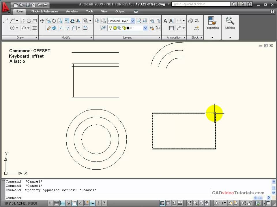
1. Command Line Input:
The most straightforward method for using the OFFSET command is through command line input. To create parallel geometry using the command line, follow these steps:
- Type “OFFSET” in the command line and press Enter to activate the OFFSET command.
- Specify the offset distance by entering a value or selecting a reference distance from existing geometry.
- Select the object or objects you want to offset by clicking on them or selecting them from the drawing area.
- Specify the side of the object from which you want to create the offset geometry.
- Press Enter to complete the offset operation.
2. Ribbon Interface:
AutoCAD’s Ribbon interface provides a graphical user interface for accessing commands and tools. To use the OFFSET command from the Ribbon interface, follow these steps:
- Navigate to the Home tab on the Ribbon.
- Click on the Modify panel to expand it.
- Click on the Offset icon to activate the OFFSET command.
- Specify the offset distance and side of the object from which you want to create the offset geometry using the options provided in the Ribbon interface.
- Select the object or objects you want to offset.
- Click OK or press Enter to complete the offset operation.
3. Toolbar or Tool Palette:
Users can also access the OFFSET command from toolbars or tool palettes for quick access and convenience. Simply click on the Offset tool icon in the toolbar or tool palette to activate the OFFSET command and follow the prompts to create parallel geometry.
Key OFFSET Command Options:
When using the OFFSET command in AutoCAD, users can specify various options and parameters to customize the offset operation according to their requirements. Key options include:
- Offset Distance: Specify the distance at which to create the parallel geometry, allowing for uniform or non-uniform offsets based on the specified distance.
- Side Selection: Specify the side of the object from which to create the offset geometry, enabling offsets to be created inside, outside, or both sides of the object.
- Multiple Offset: Optionally, enable multiple offset mode to create multiple parallel copies of the selected object at different distances, streamlining the creation of complex offset geometry.
Advanced Techniques:
In addition to basic offset methods, AutoCAD offers advanced techniques and tools for enhancing the OFFSET command and efficiency:
- Offset with Trim: Use the OFFSET command in conjunction with trimming tools to trim the offset geometry to intersecting objects automatically, providing clean and precise offsets.
- Offset with Join: Apply the OFFSET command with the join option to create offset polylines and automatically join them with the original polyline, maintaining continuity and integrity of the geometry.
- Offset with Layers: Utilize layers to organize and manage offset geometry separately from the original objects, enabling better control and visibility of offset elements within the drawing.
Best Practices:
To achieve optimal results when using the OFFSET command in AutoCAD, it’s essential to adhere to the following best practices:
- Plan and Preview: Before creating offsets, carefully plan the desired offset distances, directions, and geometry, considering factors such as object relationships and design intent.
- Use Consistent Parameters: Maintain consistency in offset parameters such as distance, side selection, and multiple offset mode to ensure uniformity and accuracy in the offset operation.
- Optimize Object Selection: Select objects efficiently for offsetting by using selection sets, filters, or object grouping, streamlining the offset operation and minimizing errors.
- Review and Verify: Review offset geometry for accuracy and completeness before finalizing drawings, verifying distances, directions, and relationships to ensure compliance with design specifications.
Conclusion:
In conclusion, mastering the OFFSET command in AutoCAD empowers designers and drafters to create parallel geometry with precision and efficiency. By understanding the various methods, options, and best practices for using the OFFSET command, users can generate offset geometry with ease, facilitating the creation of complex shapes and boundaries within drawings. With AutoCAD’s versatile tools and features, designers can achieve efficient offset operations and enhance productivity in their drawings and designs.