Exploring the PLC I/O Utility in Autodesk Electrical: A Comprehensive Guide
The PLC I/O Utility in Autodesk Electrical is a powerful tool that simplifies the integration of Programmable Logic Controller (PLC) input/output (I/O) modules into electrical designs. By streamlining the process of configuring and managing I/O points, this utility enhances efficiency, accuracy, and collaboration in PLC-based control system design. In this extensive guide, we will delve into the intricacies of using the PLC I/O Utility in Autodesk Electrical, providing detailed instructions, best practices, and expert tips to help you master this essential aspect of electrical design.
Understanding the Significance of PLC I/O Configuration
PLC I/O configuration is a critical step in the design of control systems, as it defines the interface between the PLC and external devices such as sensors, actuators, switches, and motors. The significance of PLC I/O configuration encompasses several key areas:
- Functionality: Configuring I/O modules enables the PLC to send and receive signals from external devices, facilitating control and automation functions.
- Interoperability: Proper configuration ensures compatibility and interoperability between PLCs and connected devices, minimizing integration issues and system errors.
- Scalability and Flexibility: The ability to easily configure and manage I/O points allows for scalability and flexibility in system design, accommodating changes and expansions as needed.
Using the PLC I/O Utility in Autodesk Electrical
Now, let’s explore the step-by-step process of using the PLC I/O Utility within Autodesk Electrical:
Step 1: Access PLC I/O Utility
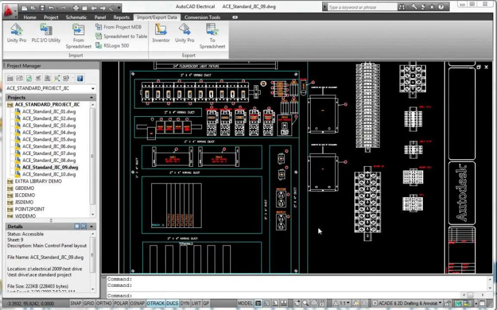
- Utility Interface: Navigate to the PLC I/O Utility interface within Autodesk Electrical, typically located in the “Utilities” or “PLC” menu.
- PLC Selection: Choose the PLC model or manufacturer for which you wish to configure I/O modules.
Step 2: Configure I/O Modules
- Module Selection: Select the specific I/O modules required for the application from the PLC manufacturer’s catalog or library.
- Placement: Drag and drop I/O modules onto the virtual rack or chassis within the utility interface, arranging them according to the physical layout of the control panel.
Step 3: Assign I/O Points
- Point Allocation: Allocate I/O points to the modules based on the requirements of the control system and the functionality of connected devices.
- Digital and Analog Inputs/Outputs: Specify whether each point is a digital input, digital output, analog input, or analog output, as well as its addressing scheme and configuration parameters.
Step 4: Validate Configuration
- Validation Checks: Perform validation checks to ensure that the configured I/O modules and points align with project requirements, PLC specifications, and industry standards.
- Error Detection: Identify and resolve any errors or conflicts in the configuration, such as overlapping addresses or incompatible module combinations.
Step 5: Export Configuration
- Export Options: Choose the desired format for exporting the I/O configuration data, such as PLC programming software formats (e.g., Ladder Logic, Function Block Diagram) or manufacturer-specific file formats.
- Save and Export: Save the configuration data to the designated location for use in PLC programming and integration with control systems.
Best Practices for Using the PLC I/O Utility
To optimize the use of the PLC I/O Utility in Autodesk Electrical, consider the following best practices:
Thorough Planning and Analysis
- System Requirements: Conduct a thorough analysis of system requirements, device specifications, and application scenarios before configuring I/O modules.
- Modular Design: Adopt a modular design approach to I/O configuration, breaking down complex systems into smaller, manageable units for easier configuration and maintenance.
Collaboration and Communication
- Cross-Functional Collaboration: Collaborate with PLC programmers, system integrators, and end-users to ensure that the I/O configuration meets the needs and expectations of all stakeholders.
- Documentation and Documentation: Document the I/O configuration process comprehensively, including module selection criteria, point allocations, and validation results, for future reference and auditing purposes.
Testing and Validation
- Simulation and Testing: Use simulation tools and virtual environments to test and validate the configured I/O modules and points before deployment in real-world applications.
- Feedback and Iteration: Gather feedback from end-users and stakeholders during the testing phase, and iterate on the configuration as needed to address any issues or concerns.
Conclusion
The PLC I/O Utility in Autodesk Electrical is a valuable tool for configuring and managing I/O modules in PLC-based control systems. By following the steps outlined in this guide and adhering to best practices, you can streamline the process of PLC I/O configuration, ensure compatibility and interoperability with connected devices, and optimize the performance and reliability of control systems. Whether you’re designing control panels for industrial automation, building management systems, or process control applications, proficiency in using the PLC I/O Utility will empower you to deliver superior results and exceed client expectations.