Mastering Kinematic Analysis in MSC Adams: A Comprehensive Guide
Introduction: MSC Adams is a leading multibody dynamics simulation software used by engineers and designers for virtual prototyping and dynamic analysis of mechanical systems. With its advanced capabilities for modeling and simulating complex kinematic and dynamic behaviors, MSC Adams enables engineers to optimize designs, predict performance, and validate mechanisms before physical prototyping. In this comprehensive guide, we’ll explore the intricacies of performing kinematic analysis in MSC Adams, covering everything from model setup to results interpretation and optimization.
Section 1: Understanding Kinematic Analysis 1.1 Introduction to Kinematic Analysis: Kinematic analysis is a fundamental aspect of mechanical engineering that focuses on the motion and behavior of mechanical systems without considering the forces and torques acting on them. In MSC Adams, kinematic analysis involves simulating the motion of interconnected rigid bodies and joints to understand how mechanisms move and interact with each other. Kinematic analysis is essential for evaluating motion characteristics, such as velocity, acceleration, and displacement, and predicting system behavior under various operating conditions.
1.2 Applications of Kinematic Analysis: Kinematic analysis is used in a wide range of engineering applications, including robotics, automotive systems, aerospace mechanisms, and industrial machinery. Engineers use kinematic analysis to optimize the design of mechanisms, analyze motion paths, evaluate clearance and interference, and predict system performance. In MSC Adams, kinematic analysis is applied to model and simulate complex mechanical systems, such as linkages, suspensions, drivetrains, and articulated robots, to understand their motion characteristics and behavior.
Section 2: Setting up Kinematic Models in MSC Adams 2.1 Building the Kinematic Model: Start by building the kinematic model of your mechanical system in MSC Adams using the modeling tools available. Define the rigid bodies, joints, and constraints that represent the components and connections of your mechanism. Use CAD data import or built-in geometry creation tools to define the geometry and shape of individual components, and assemble them into a kinematic model using joints and connections.
2.2 Defining Joints and Constraints: Define joints and constraints to represent the connections between rigid bodies in your kinematic model accurately. MSC Adams provides a variety of joint types, including revolute, prismatic, cylindrical, spherical, and planar joints, to model different types of motion and constraints. Specify joint parameters such as axis of rotation, limits, stiffness, and damping to define the behavior and characteristics of each joint in the model. Use constraints such as fixed, translational, and rotational constraints to restrict degrees of freedom and enforce geometric relationships between components.
Section 3: Applying Kinematic Loads and Boundary Conditions 3.1 Kinematic Inputs: Define kinematic inputs such as velocities, displacements, and motion profiles to drive the motion of your kinematic model in MSC Adams. Specify input functions, motion curves, or external drivers to control the motion of selected joints or components in the model. Use time-dependent functions or user-defined profiles to simulate complex motion patterns, such as sinusoidal motion, step inputs, or custom motion sequences, and analyze the response of the mechanism under varying input conditions.
3.2 Boundary Conditions: Define boundary conditions to represent external constraints or interactions that affect the motion of your kinematic model in MSC Adams. Specify constraints such as ground contacts, fixed supports, or prescribed motion to simulate the environment and loading conditions that the mechanism operates in. Use friction models, contact algorithms, and interaction forces to model realistic interactions between components and surfaces and analyze the effects of friction, inertia, and external forces on system behavior.
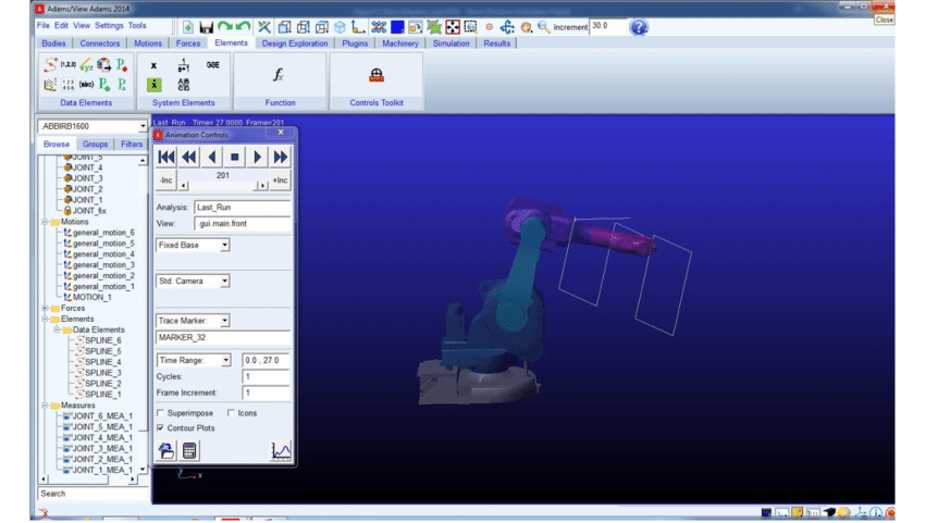
Section 4: Running Kinematic Simulations and Analyzing Results 4.1 Running Simulations: Once the kinematic model setup is complete, run simulations in MSC Adams to analyze the motion and behavior of your mechanical system. Define simulation parameters such as time step, integration method, and solver settings to control the accuracy and stability of the simulation. Monitor the simulation progress and check for convergence to ensure that the results are reliable and accurate.
4.2 Analyzing Results: After the simulation is complete, analyze the results to gain insights into the kinematic behavior of your mechanical system. Visualize motion trajectories, displacement profiles, velocity profiles, and acceleration profiles to understand how individual components move and interact with each other over time. Use animation tools, graphs, and plots to visualize and interpret simulation results effectively, and identify critical motion characteristics, such as dwell points, singularities, and dynamic instabilities.
Section 5: Optimizing Kinematic Designs and Iterating 5.1 Design Optimization: Use the insights gained from kinematic analysis to optimize the design of your mechanical system in MSC Adams. Identify areas for improvement, such as reducing friction, minimizing clearance, increasing efficiency, or enhancing performance, and explore design modifications to achieve these objectives. Experiment with different joint configurations, motion profiles, and component layouts to optimize system behavior and meet design requirements.
5.2 Iterative Analysis: Perform iterative kinematic analysis in MSC Adams to evaluate the impact of design changes on system behavior and performance. Modify the kinematic model geometry, joint parameters, or motion inputs as needed, and rerun simulations to assess the effectiveness of design modifications. Iterate through multiple design iterations, refining the design based on simulation results, until satisfactory performance is achieved.
Conclusion: Kinematic analysis is a powerful tool for understanding the motion and behavior of mechanical systems in engineering design. With MSC Adams, engineers can model and simulate complex kinematic systems, analyze motion characteristics, and optimize designs for improved performance and efficiency. By mastering the fundamentals of kinematic analysis in MSC Adams and exploring advanced techniques and workflows, engineers can unleash their creativity and innovation to develop cutting-edge mechanical systems that meet the demands of modern engineering challenges. With practice, experimentation, and continuous learning, engineers can leverage the full potential of MSC Adams to optimize, innovate, and excel in mechanical system design and development.