Mastering Drawing Creation in SolidWorks: A Comprehensive Guide

Introduction: SolidWorks, a leading computer-aided design (CAD) software, empowers engineers and designers to transform 3D models into detailed and precise technical drawings. Drawings serve as essential documentation for communicating design intent, specifying manufacturing instructions, and facilitating quality control processes. In this comprehensive guide, we’ll explore the intricacies of creating drawings in SolidWorks, covering fundamental concepts, essential techniques, and advanced strategies to help you master this critical aspect of the design process.
Understanding Drawing Creation in SolidWorks: Drawing creation in SolidWorks involves the translation of 3D models into 2D representations that convey geometric dimensions, tolerances, annotations, and other essential information required for manufacturing and assembly. Before delving into the specifics of drawing creation, it’s crucial to grasp some foundational concepts:
- Model-Based Definition (MBD):
- SolidWorks supports Model-Based Definition (MBD), where 3D models serve as the primary source of product definition, eliminating the need for traditional 2D drawings. MBD enhances communication, reduces errors, and streamlines the design-to-manufacturing process.
- Drawing Views:
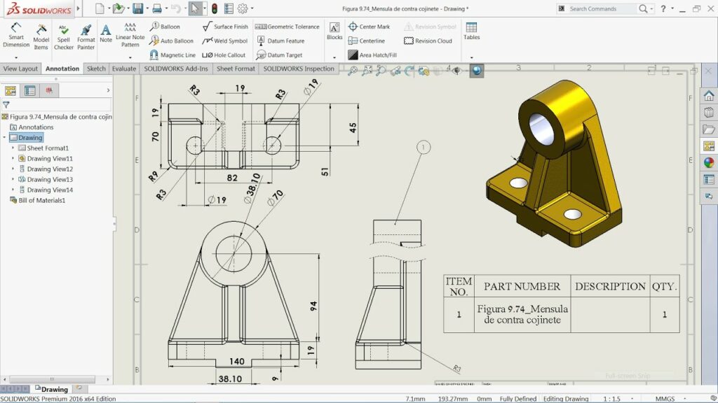
- Drawing views are 2D representations of the 3D model from different perspectives, such as front, top, side, and isometric views. SolidWorks provides tools for creating orthographic views, section views, detail views, and auxiliary views to depict the geometry accurately.
- Annotations and Dimensions:
- Annotations and dimensions are essential elements of drawings that provide critical information about the design, including dimensions, tolerances, notes, symbols, and GD&T (Geometric Dimensioning and Tolerancing). SolidWorks offers a comprehensive set of annotation tools for adding text, symbols, leaders, and geometric tolerances to drawings.
Creating Drawings in SolidWorks: SolidWorks offers intuitive tools for creating drawings, allowing users to generate detailed and accurate documentation quickly. Let’s explore the essential steps for creating drawings:
- Open a New Drawing Document:
- Start by opening a new drawing document in SolidWorks. You can access the New Document dialog from the File menu or the Welcome screen. Choose the drawing template that best suits your design requirements, such as ANSI, ISO, or custom templates, and click OK to open the drawing environment.
- Insert Drawing Views:
- Once the drawing document is open, insert drawing views to represent the 3D model geometry. Use the View Palette or the Insert Drawing View command to add orthographic, isometric, section, and detail views to the drawing sheet. Position and arrange drawing views as needed to convey the design effectively.
- Define Drawing Scale:
- Specify the drawing scale to ensure that the dimensions and annotations are displayed at the appropriate size relative to the real-world dimensions of the model. SolidWorks provides options for selecting standard scales or custom scales based on design requirements and sheet size.
- Add Annotations and Dimensions:
- Populate the drawing views with annotations, dimensions, and other necessary information to convey design intent and manufacturing requirements. Use the Smart Dimension tool, Dimension Palette, and Annotation Toolbar to add dimensions, geometric tolerances, notes, symbols, and other annotations to the drawing.
- Customize Drawing Properties:
- Customize drawing properties such as title block, sheet format, and border to comply with company standards and industry conventions. SolidWorks provides tools for adding custom title blocks, revision tables, part lists, and other drawing elements to enhance documentation clarity and completeness.
Advanced Drawing Techniques: In addition to basic drawing tools, SolidWorks offers advanced techniques to enhance drawing creation workflows and achieve precise documentation objectives:
- Custom Drawing Templates:
- Create custom drawing templates with predefined settings, formats, and annotations to standardize drawing creation across projects and teams. Custom templates streamline the drawing process, ensure consistency, and maintain company branding and standards.
- Drawing Standards and Conventions:
- Adhere to industry standards and drawing conventions, such as ASME Y14.5, ISO 128, and company-specific guidelines, to ensure compliance with regulatory requirements and facilitate interoperability with suppliers and manufacturers.
- Model-Based Definition (MBD):
- Embrace Model-Based Definition (MBD) practices to leverage 3D annotations, PMI (Product and Manufacturing Information), and GD&T directly within the 3D model. MBD reduces reliance on 2D drawings, improves communication, and streamlines the design-to-manufacturing process.
Best Practices for Drawing Creation: To maximize efficiency and maintain documentation integrity when creating drawings in SolidWorks, it’s essential to adhere to best practices:
- Design Intent and Clarity:
- Communicate design intent clearly through well-organized drawings with logical arrangement, consistent annotation styles, and descriptive labels. Ensure that drawings are easy to interpret, understand, and follow by users involved in manufacturing, inspection, and assembly processes.
- Dimensioning and Tolerancing:
- Apply geometric dimensioning and tolerancing (GD&T) principles to specify dimensional requirements, tolerances, and inspection criteria accurately. Use appropriate dimensioning techniques, such as baseline dimensioning, chain dimensioning, and ordinate dimensioning, to convey geometric relationships effectively.
- Revision Control and Documentation:
- Implement revision control procedures to manage changes and updates to drawings effectively. Use revision tables, revision clouds, and change tracking features to document revisions, track revision history, and communicate changes to stakeholders and team members.
- Collaboration and Review:
- Collaborate with design team members, manufacturing engineers, and stakeholders to review and validate drawings for accuracy, completeness, and compliance with design requirements. Use tools like eDrawings, PDF markup, and SolidWorks PDM to facilitate collaboration and streamline review processes.
Conclusion: Drawing creation is a critical aspect of the design process in SolidWorks, enabling engineers and designers to document and communicate design intent effectively. By mastering the tools and techniques for creating drawings, you can enhance your design capabilities, streamline your documentation workflow, and produce high-quality documentation that meets design requirements and manufacturing standards. Whether you’re a novice or an experienced SolidWorks user, understanding the principles of drawing creation and applying best practices will elevate your documentation proficiency and enable you to convey design intent with precision and clarity.


