Comprehensive Guide to Inserting Components into Assemblies in SolidWorks

Introduction: SolidWorks, a leading computer-aided design (CAD) software, provides engineers and designers with powerful tools to create complex assemblies consisting of multiple components. Inserting components into assemblies is a fundamental step in the design process, allowing users to assemble parts, define relationships, and visualize the final product. In this comprehensive guide, we’ll explore the intricacies of inserting components into assemblies in SolidWorks, covering fundamental concepts, essential techniques, and advanced strategies to help you master this critical aspect of CAD design.
Understanding Component Insertion in SolidWorks: Component insertion in SolidWorks involves adding individual parts, subassemblies, or other assemblies into an assembly document to create a complete product or system. Each inserted component retains its individual properties, dimensions, and relationships, allowing for precise modeling and assembly. Before delving into the specifics of inserting components, it’s crucial to grasp some foundational concepts:
- Assembly Environment:
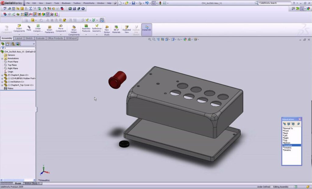
- The assembly environment in SolidWorks provides a workspace for assembling components, defining relationships, and creating complex systems. Users can navigate the assembly environment using tools such as the FeatureManager design tree, graphics area, and assembly toolbar.
- Inserting Parts:
- Parts can be inserted into assemblies using various methods, including browsing existing files, creating new components, or dragging components from the Design Library. SolidWorks supports a wide range of file formats for component insertion, including native SolidWorks files, STEP, IGES, and more.
- Component Relationships:
- When inserting components into assemblies, users can define mate relationships to constrain the position and orientation of components relative to each other. Mate relationships include coincident, parallel, perpendicular, concentric, and tangent, among others, and help ensure that components are properly aligned within the assembly.
Inserting Components into Assemblies in SolidWorks: SolidWorks offers multiple methods for inserting components into assemblies, each suited to different design requirements and preferences. Let’s explore the essential tools and techniques for inserting components:
- Insert Component Command:
- The Insert Component command is the primary method for inserting components into assemblies in SolidWorks. Users can access the Insert Component command from the Assembly tab or the right-click context menu and choose from options to insert existing parts, subassemblies, or other assemblies.
- Browse and Insert:
- To insert an existing component into an assembly, users can browse their computer or network for the desired file and select it for insertion. SolidWorks provides options to specify the insertion point, orientation, and scale of the inserted component relative to the assembly.
- Create New Part:
- SolidWorks allows users to create new parts directly within an assembly document using the New Part command. This method is useful for designing components that are unique to the assembly or for creating placeholder components before detailed modeling.
- Drag and Drop:
- Users can drag components from the Design Library or Windows Explorer directly into the assembly graphics area to insert them. SolidWorks provides visual feedback during the drag operation, allowing users to position components accurately before dropping them into the assembly.
Advanced Component Insertion Techniques: In addition to basic insertion methods, SolidWorks offers advanced techniques to enhance component insertion workflows and achieve precise design objectives:
- Copy with Mates:
- The Copy with Mates command allows users to insert multiple instances of a component while automatically applying predefined mate relationships. This method streamlines the insertion process for repetitive components and ensures consistent positioning within the assembly.
- Assembly Configurations:
- SolidWorks supports assembly configurations, allowing users to create multiple variations of an assembly with different component arrangements and states. Users can define configurations to show or hide components, suppress features, or change mate relationships dynamically.
- Smart Components:
- Smart Components in SolidWorks are predefined assemblies that contain mate relationships and configurations. Users can insert smart components into assemblies and automatically mate them to other components, streamlining the assembly process and ensuring design consistency.
Best Practices for Component Insertion: To maximize efficiency and maintain design integrity when inserting components into assemblies in SolidWorks, it’s essential to adhere to best practices:
- Component Naming and Organization:
- Use descriptive names and organize components logically within the assembly hierarchy using folders, subassemblies, and naming conventions. Keep related components together and use consistent naming conventions to facilitate navigation and management of the assembly.
- Standardized Placement:
- Establish standardized placement guidelines for inserting components, such as default insertion points, orientations, and scales. Consistent component placement improves assembly efficiency, reduces errors, and ensures compatibility with mating components.
- Validate and Test:
- Regularly validate inserted components to ensure that they meet design requirements and assembly constraints. Use tools like interference detection, motion analysis, and physical testing to verify component fit, alignment, and functionality within the assembly.
- Collaboration and Communication:
- Collaborate with team members, stakeholders, and suppliers to review and validate the assembly design. Use tools like eDrawings, 3D PDFs, and SolidWorks PDM to share and collaborate on assembly files securely and communicate design specifications effectively.
Conclusion: Inserting components into assemblies is a fundamental aspect of product design in SolidWorks, enabling engineers and designers to create complex systems with precision and efficiency. By mastering the tools and techniques for inserting components, you can enhance your design.


