Mastering Circuit Design with the Circuit Builder Tool in Autodesk Electrical: A Comprehensive Guide
The Circuit Builder tool in Autodesk Electrical is a powerful feature that enables designers to create and customize electrical circuits with precision and efficiency. By providing intuitive controls and extensive libraries of components, the Circuit Builder tool streamlines the process of circuit design, allowing designers to focus on creativity and innovation. In this comprehensive guide, we will explore the intricacies of using the Circuit Builder tool in Autodesk Electrical, providing detailed instructions, best practices, and expert tips to help you master this essential aspect of electrical design.
Understanding the Significance of the Circuit Builder Tool
The Circuit Builder tool plays a pivotal role in electrical design, offering several key benefits:
- Efficiency: The Circuit Builder tool accelerates the creation of electrical circuits by providing pre-configured components and intuitive design features.
- Precision: Designers can create circuits with precision and accuracy, ensuring that components are properly connected and configured.
- Flexibility: The tool offers flexibility to customize circuit layouts, component properties, and wiring configurations to meet specific project requirements.
Using the Circuit Builder Tool in Autodesk Electrical
Now, let’s delve into the step-by-step process of using the Circuit Builder tool within Autodesk Electrical:
Step 1: Accessing the Circuit Builder Tool
- Toolbar Access: Navigate to the toolbar or menu within Autodesk Electrical to access the Circuit Builder tool.
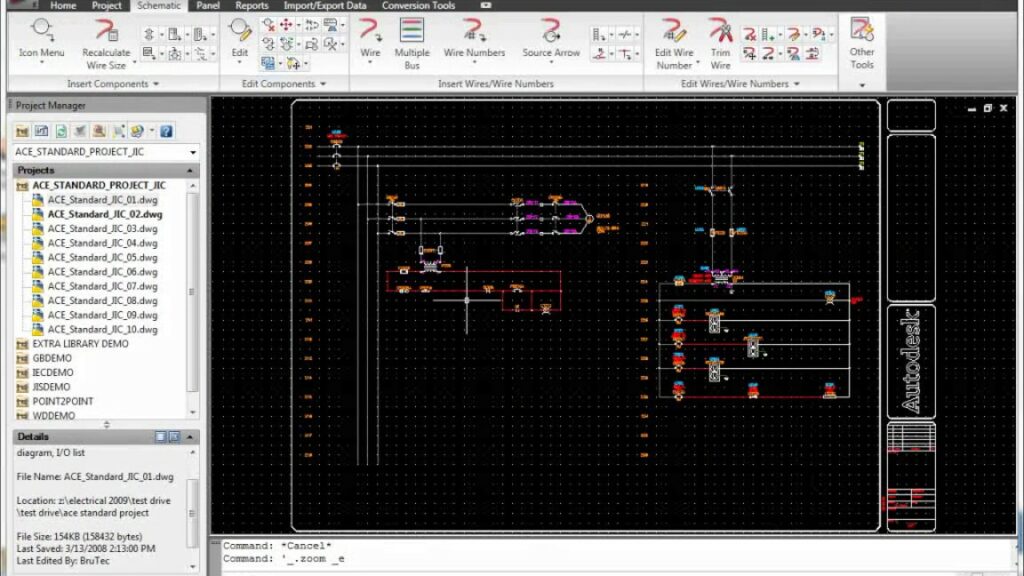
- Workspace Setup: Configure the workspace to display the Circuit Builder interface, which typically includes a library of components and a canvas for circuit design.
Step 2: Selecting Components
- Component Library: Browse the component library to select the desired components for the circuit, including switches, relays, sensors, and other devices.
- Drag-and-Drop: Drag and drop components from the library onto the canvas to begin assembling the circuit.
Step 3: Configuring Component Properties
- Properties Panel: Access the properties panel to configure properties such as voltage ratings, current capacities, and operational parameters for each component.
- Parameter Adjustment: Adjust component parameters as needed to match project specifications and design requirements.
Step 4: Connecting Components
- Wiring Tools: Utilize wiring tools such as lines, wires, and connectors to establish connections between components.
- Logical Connections: Ensure that connections are made logically and according to electrical principles, such as proper polarity and continuity.
Step 5: Validating and Testing
- Validation Checks: Perform validation checks to ensure that the circuit layout adheres to design rules, safety standards, and regulatory requirements.
- Simulation: Utilize simulation tools to test the functionality and performance of the circuit under various operating conditions.
Step 6: Documenting and Saving
- Documentation: Document the circuit design by adding annotations, labels, and notes to provide context and clarity for future reference.
- Save and Export: Save the circuit design to the project file or export it in a compatible format for sharing, collaboration, and integration with other design tools.
Best Practices for Using the Circuit Builder Tool
To optimize the use of the Circuit Builder tool in Autodesk Electrical, consider the following best practices:
Planning and Preparation
- Pre-Planning: Plan the circuit layout and component selection before starting the design process to streamline workflow and minimize revisions.
- Component Verification: Verify component specifications and compatibility with project requirements to avoid design errors and inconsistencies.
Organization and Efficiency
- Library Management: Organize component libraries into categories and subcategories for easy navigation and retrieval.
- Keyboard Shortcuts: Familiarize yourself with keyboard shortcuts and hotkeys to expedite common tasks and operations within the Circuit Builder tool.
Collaboration and Communication
- Team Collaboration: Collaborate with team members, engineers, and stakeholders to gather input, feedback, and insights during the circuit design process.
- Clear Documentation: Document circuit designs comprehensively, including design rationale, assumptions, and constraints, to facilitate communication and knowledge transfer.
Conclusion
The Circuit Builder tool in Autodesk Electrical empowers designers to create intricate and precise electrical circuits with ease and efficiency. By following the steps outlined in this guide and adhering to best practices, you can harness the full potential of the Circuit Builder tool to streamline circuit design workflows, optimize component selection and configuration, and ensure compliance with project requirements and industry standards. Whether you’re designing circuits for control systems, automation applications, or power distribution networks, proficiency in using the Circuit Builder tool will enable you to deliver superior results and exceed client expectations.